


Hello everyone! Welcome again. In this article, I will be discussing what exactly is assembly language, a brief overview of a simple processor, assembly language code and a lab I completed. So before we begin, let’s first dive into what exactly assembly language is.
What is Assembly Language?
If you’re a programmer or at least know of the basics of computers, you know that the software we use is coded in some arbitrary language. For example, when making websites, the front end (what you see) can be coded in JavaScript, React, or even Python! Likewise, when we dive deeper into computer hardware such as the CPU, we can make the CPU perform actions using assembly language!
Look at this figure below for a better understanding:
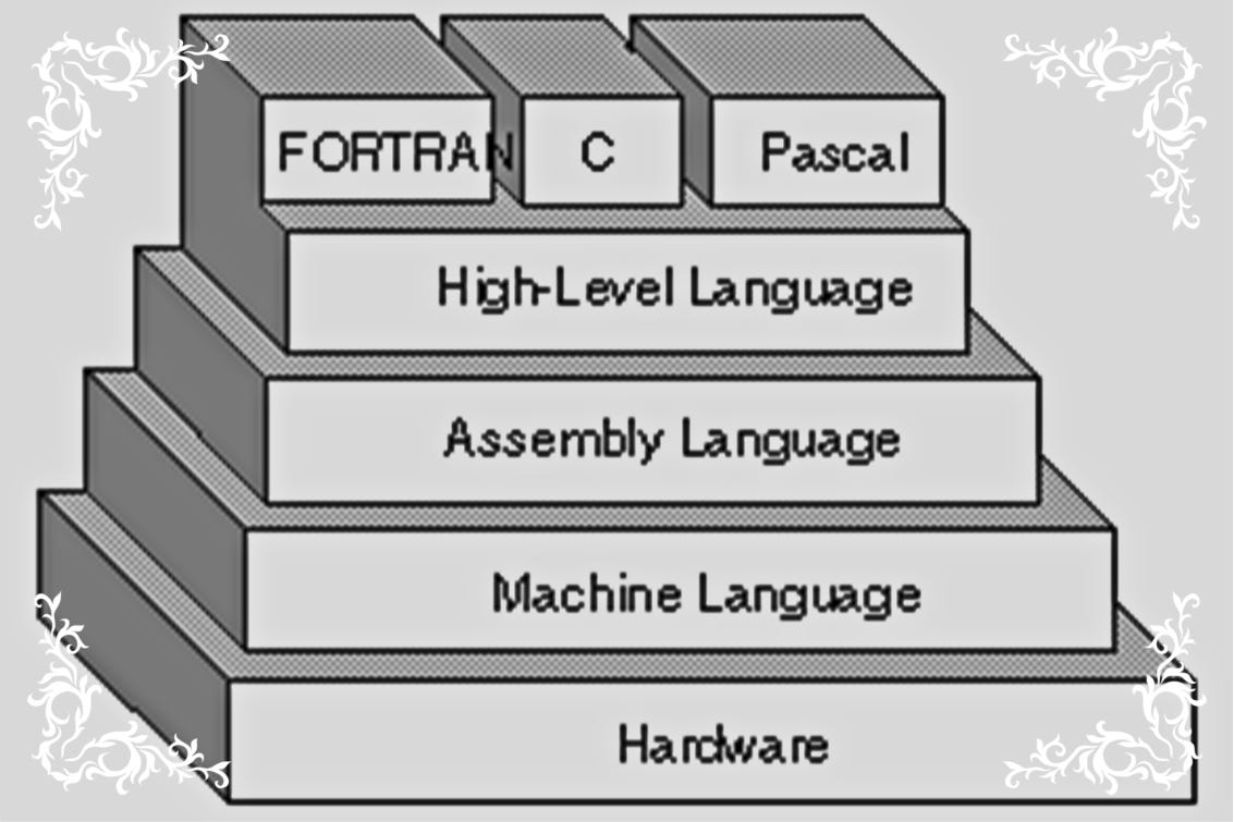
Before we get into the specifics of assembly language, let’s discuss an old processor called the 6502 processor.
What is the 6502 processor?
The 6502 processor was created in thre 1970s and was an affordable CPU that had a very simple design with minimal instructions, but this is what made it affordable and easy to use. It is by no means a high performing processor as it is an 8-bit processor. To learn more about this processor, click here.
Assembly Language Coding
Like programming in C, Java, Python, etc. Assembly Language coding also has several commands that perform certain actions. It is important to note though that in assembly language, we are interacting with the CPU itself!
To summarize what we are doing, the CPU has certain components inside called registers. These registers can hold data and process data. From a coding perspective, we use certain instructions that perform actions on the CPU. Check out the table below for more information
| Command | Action |
| LDA #21 | Loads the accumulator register with a value you specify |
| LDX $25 | Loads the x register with a value you specify |
| STA $00 | Loads the value inside the accumulator at memory address $00 |
The 6502 processor has over 50 instructions/commands, this article will not cover all of these. But please feel free to click here to learn more about all of the instructions available.
Lab 1
This lab will be divided into several sections. In the first section we will be going over the performance of assembly language code submitted by my professor.
Calculating Performance
The code below is assembly language code submitted by Professor Chris Tyler. This code simply fills 6 pages of memory with the color yellow by looping around it.
     lda #$00    ; set a pointer in memory location $40 to point to $0200
     sta $40        ; ... low byte ($00) goes in address $40
     lda #$02
     sta $41        ; ... high byte ($02) goes into address $41
     lda #$07    ; colour number
     ldy #$00    ; set index to 0
 loop:    sta ($40),y    ; set pixel colour at the address (pointer)+Y
     iny        ; increment index
     bne loop    ; continue until done the page (256 pixels)
     inc $41        ; increment the page
     ldx $41        ; get the current page number
     cpx #$06    ; compare with 6
     bne loop    ; continue until done all pages
To calculate performance, we will assume a 1 MHz clock speed. We will also need to identify the following for each line of code:
# of Cycles [This can be found here]
Counts [This is determined logically]
Alt-Cycles
Alt-Count
Execution time for Professors code:
Below is a table I constructed identifying the total execution time of the code above:
| Bytes | Cycles | Count | Alt-cycles | Alt-count | Total | ||
| lda #$00 | 2 | 2 | 1 | 2 | |||
| sta $40 | 2 | 3 | 1 | 3 | |||
| lda #$02 | 2 | 2 | 1 | 2 | |||
| sta $41 | 2 | 3 | 1 | 3 | |||
| lda #$07 | 2 | 2 | 1 | 2 | |||
| ldy #$00 | 2 | 2 | 1 | 2 | |||
| loop: sta ($40), y | 2 | 6 | 1024 | 6144 | |||
| iny | 1 | 2 | 1024 | 2048 | |||
| bne loop | 2 | 3 | 1020 | 2 | 4 | 3068 | |
| inc $41 | 2 | 5 | 4 | 20 | |||
| ldx $41 | 2 | 3 | 4 | 12 | |||
| cpx #$06 | 2 | 2 | 4 | 8 | |||
| bne loop | 2 | 3 | 3 | 2 | 1 | 11 | |
| Total Cycles | 11325 | ||||||
| Clock Speed | 1 | MHz | |||||
| Cycle Time | 0.000001 | s | |||||
| Execution time | 0.011325 | s | |||||
| 11.325 | mS | ||||||
| 11325 | uS | ||||||
| Bytes Calculation | |||||||
| Code | 25 | Bytes | |||||
| Screen | 1536 | Bytes | |||||
| Total Bytes | 1561 | Bytes |
Viewing the able above, it takes approximately 11325 micro-seconds for this code to execute.
Total Memory Usage
The total memory usage is calculated by finding the number of bytes from the code and the screen. The number of bytes per instruction can be found here. By summing the bytes from the code and screen, we find that the total memory usage is 1049 bytes.
Now, you may be thinking you wont even be able to tell, who cares. However, in some instances it is best we try to optimize this code to make our program run faster.
What if I were to tell you we can reduce this code by 50%!
Making the code more efficient
When you breakdown the code provided above, you realize that the code performs actions for each page, which can be a time consuming process. Therefore, I took a step back and thought how can I make this code more efficient?
I realized that my goal is to fill the screen which can be done in 4 pages. Therefore, if I create pointers for each page and use one loop to fill them all simultaneously I can drastically reduce the time spent!
Below is the code I created:
; Set the memory locations we need
; The fastest way to do this would be to do all pages simultaneously. So to do that, lets initialiuze each page

; Page 1
LDA #$00 ; For the first line in memory
STA $40; Storing Accumulator data at address $40
LDA #$02 ; Load accumulator with value $02
STA $41; Storing accumulator data at address $41

; Page 2
LDA #$00
STA $42
LDA #$03
STA $43

; Page 3
LDA #$00
STA $44
LDA #$04
STA $45

; Page 4
LDA #$00
STA $46
LDA #$05
STA $47

; Set the color we want
LDA #$07 ;

; Y will store each value within each row
LDY #$00 ; First position

; Loop until each pixel is filled inside each element in each row for each page simultaneously
LOOP:
STA ($40), y
STA ($42), y
STA ($44), y
STA ($46), y
INY
BNE LOOP
I also created a table to display the execution time and total memory usage:
| Commands | Bytes | Cycles | Count | Alt-cycles | Alt-count | Total | |
| LDA #$00 | 2 | 2 | 1 | 2 | |||
| STA $40 | 2 | 3 | 1 | 3 | |||
| LDA #$02 | 2 | 2 | 1 | 2 | |||
| STA $41 | 2 | 3 | 1 | 3 | |||
| LDA #$00 | 2 | 2 | 1 | 2 | |||
| STA $42 | 2 | 3 | 1 | 3 | |||
| LDA #$03 | 2 | 2 | 1 | 2 | |||
| STA $43 | 2 | 3 | 1 | 3 | |||
| LDA #$00 | 2 | 2 | 1 | 2 | |||
| STA $44 | 2 | 3 | 1 | 3 | |||
| LDA #$04 | 2 | 2 | 1 | 2 | |||
| STA $45 | 2 | 3 | 1 | 3 | |||
| LDA #$00 | 2 | 2 | 1 | 2 | |||
| STA $46 | 2 | 3 | 1 | 3 | |||
| LDA #$05 | 2 | 2 | 1 | 2 | |||
| STA $47 | 2 | 3 | 1 | 3 | |||
| LDA #$07 | 2 | 2 | 1 | 2 | |||
| LDY #$00 | 2 | 2 | 1 | 2 | |||
| LOOP: STA ($40), y | 2 | 6 | 256 | 1536 | |||
| STA ($42), y | 2 | 6 | 256 | 1536 | |||
| STA ($44), y | 2 | 6 | 256 | 1536 | |||
| STA ($46), y | 2 | 6 | 256 | 1536 | |||
| INY | 1 | 2 | 256 | 512 | |||
| BNE LOOP | 2 | 2 | 255 | 3 | 510 | ||
| Total Cycles | 7210 | ||||||
| Clock Speed | 1 | MHz | |||||
| Cycle Time | 0.000001 | s | |||||
| Execution time | 0.00721 | s | |||||
| 7.21 | mS | ||||||
| 7210 | uS | ||||||
| Bytes Calculation | |||||||
| Code | 47 | ||||||
| Screen | 1024 | ||||||
| Total | 1071 |
Execution Time: 7210 micro-seconds
Total Memory Usage: 1071 bytes
As you can see there is a substantial execution time difference when comparing the code above with the previous one!
Modifying the code to change the color
To change the color of the code is quite simple. I simply have to change the value present inside the accumulator to a hex value equal to light blue.
The hex value for light blue for the 6502 processor is $0e. Therefore the code will be as follows:
; Set the memory locations we need
; The fastest way to do this would be to do all pages simultaneously. So to do that, lets initialiuze each page

; Page 1
LDA #$00 ; For the first line in memory
STA $40; Storing Accumulator data at address $40
LDA #$02 ; Load accumulator with value $02
STA $41; Storing accumulator data at address $41

; Page 2
LDA #$00
STA $42
LDA #$03
STA $43

; Page 3
LDA #$00
STA $44
LDA #$04
STA $45

; Page 4
LDA #$00
STA $46
LDA #$05
STA $47

; Set the color we want
LDA #$0e ;

; Y will store each value within each row
LDY #$00 ; First position

; Loop until each pixel is filled inside each element in each row for each page simultaneously
LOOP:
STA ($40), y
STA ($42), y
STA ($44), y
STA ($46), y
INY
BNE LOOP
Set a different color for each page
To set a different color for each page is done by setting the accumulator after each page is loaded within the loop. Please view a section of the code below to get an idea:
; Loop until each pixel is filled inside each element in each row for each page simultaneously
LOOP:
LDA #$06 ; Color for page 1
STA ($40), y

; Color for page 2
LDA #$09
STA ($42), y

; Color for page 3
LDA #$03
STA ($44), y

; Color for page 4
LDA #$04
STA ($46), y

INY
BNE LOOP
Make each pixel a random color
To make each pixel a random color you can use a pseudo-random number generator. Look at the code below to get an idea:
; The pseduo-random seet
LDA #$12
STA $48

; Loop until each pixel is filled inside each element in each row for each page simultaneously
LOOP:
; Generate the random number
LDA $48
ASL
EOR $48
LSR
STA $48

STA ($40), y
STA ($42), y
STA ($44), y
STA ($46), y
INY
BNE LOOP
Experiments
What happens after adding the instruction ‘TYA’ after the loop and before ‘sta ($40), y‘?
Answer: The visual effect is a combination of different colored vertical lines. There are a total of 32 colors. This is because ‘TYA’ moves the value in Y register into accumulator A without changing the content inside Y register.
Add the instruction ‘LSR’ after TYA
Answer: This causes the same vertical lines, but the vertical lines are thicker and there are 16 colors now. This is because ‘LSR’ shifts the accumulator 1 bit to the right, thus halving the original 32 colors.Repeat the above tests with two, three, four, and five
lsrinstructions in a row. Describe and explain the effect in each case.
Answer: When adding two LSR instructions, its shifting the colors into different rows. The more LSRs you add, the less the thicker the colors got which then gives the illusion of smaller columns.Repeat the tests using
aslinstructions instead oflsrinstructions. Describe and explain the effect in each case.Answer: When doing this, it starts to change the colors because ASL moves 1 bit to the left for the accumulator and because the accumulator is holding the color value, the colors start to decrease in hex value. This means with enough ASL it will reach the color black.
The original code includes one
inyinstruction. Test with one to five consecutiveinyinstructions. Describe and explain the effect in each case. Note: it is helpful to place the Speed slider is on its lowest setting (left) for these experiments.
Answer: When adding more INY’s either, there are vertical lines present, or the screen fills up sporadically. This happens because INY is moving to the next pixel by increasing the memory addrtess. So when you add more INY’s its skipping memory addresses. Likewise, when the Y register is done the 256 steps, the base pointer moves to the next page and fills that.
Conclusion / Experiences
In conclusion, this lab taught me a variety of concepts that shaped my understanding of assembly language. I have never coded in assembly before and truthfully it was hard to grasp and I still have trouble understanding it to some extent. However, as I blog and put in the effort, things are slowly coming to mind.
This lab gave me a great understanding of what exactly assembly language is accomplishing. In addition, I learned how to use instructions to perform an action within the CPU. Lastly, I now have a much better understanding of the logic involved in assembly programming.
References
Cover image was taken from asm.sourceforge.net